| SCAN
Z – INSTRUCTIONS rev. 2 |
|
WHAT
YOU NEED
MAKING
INDICATOR STRIP
SETTING
UP THE SCANNER
SCANNING
USING
SCAN Z
EXTRA FUNCTIONS
WHAT
YOU NEED
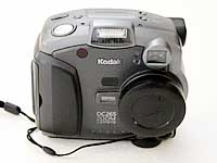
To begin scanning there are a few essential items. The first
is a digital camera. Almost any digital camera will do, as long
as it has a tripod mount hole at the base.
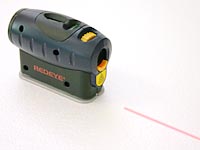
The
second is a laser line generator, or laser level. This one is a GMC Redeye Deluxe
Laser Line Generator. I grabbed it from the hardware for around
$60. It also has a standard tripod mount hole. Apparently Lowe's
is the exclusive distributor for GMC products in the US, but I have not seen this item available anywhere other than Australia. It would appear that Craftsmen have this exact same laser with different coloured plastic. Everything else about it seems identical. These are available from Sears. The product is called the Craftsman Laser Trac™ Level with Carrying Case and Laser Enhancing Glasses. (Sears item#00948251000 )
NOTE: A laser pointer will not suffice for this purpose as they only project a small dot. Laser line generators have a lens in them that splits the laser point into a vertical or horizontal line. The thinner and brighter this line is, the better.
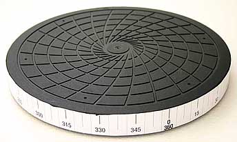
The
third item is a rotating platform or turntable of some description. This is a Vogel's 32cm rotating television stand
(TVS 032). It was
$30, and is smooth and very sturdy. I then printed out a thin indicator strip all the way around
the base with marks at regular intervals. I have placed marks
at 15 degrees
(24 segments), 7.5 degrees (48 segments) and 3.75
degrees
(96 segments).
MAKING
INDICATOR STRIP
The indicator strip can end up being very long, so it may need
to be printed in sections, and then joined together. You will
need some sort of illustration application such as Adobe Illustrator,
that will enable you to place lines at accurate increments.
STEP 1. Measure the diameter of the rotating platform.
For those of you who get your radius and diameter mixed up,
the diameter is the distance from edge to edge, slicing right
through the centre of the platform. The platform shown above
has a diameter of 317mm (12.5"). Next we need to work out
the circumference. This is easily calculated with the formula
diameter x pi (3.1415927). For my rotating platform, that would
be 317mm x 3.1415927 = 995.9 mm (39.2").
STEP 2. Armed with the circumference value, now we need
to create our indicator strip with the increment marks. I have
chosen to create my indicator strip with marks at every 3.75
degrees, 7.5 degrees and 15 degrees. This allows me to capture
the object in 24, 48 or 96 segments respectively. The number
of increments you use is entirely up to you. Perhaps you want
to scan very high resolution objects, and would like to be able
to photograph 200 segments, or perhaps you want to scan low
res objects of only 12 segments or less. Just keep in mind that
the demo version of Scan Z is limited to only 12 segments. Work
out how many increments you want, and then divide your circumference
by that figure. For my example, creating marks for 24 increments
would mean drawing a line every 41.5mm (995.9mm ÷ 24
= 41.5mm). Now you can print out the indicator strip, and stick
it to your platform with glue or double-sided tape.
NOTE: If you are a registered user of Scan Z, you can send
me the diameter of your rotating platform, and I will send you
back an eps file with the increments marked out along the circumference.
SETTING
UP THE SCANNER
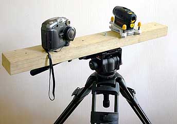
The three items will need to be set up in a triangle as seen
below.
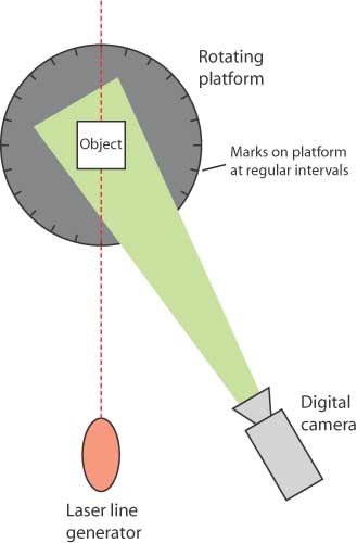
You
can mount the camera and the laser line generator onto a piece
of timber, which can then be mounted onto a tripod. A tripod
isn't entirely necessary, as long as you have a way of securing
the camera and laser in position so that they can't move during
a scan. I have successfully made a scan by simply placing all
three items onto a sturdy table. If your resources are unlimited,
you could place the camera and the laser on their own separate
tripods. The tripod mount screw at the bottom of most cameras
takes a standard 1/4" bolt, which you can purchase in a
range of lengths from any good (even bad) hardware store. If
you should require more information on this process, feel free
to send me an email.
NOTE: Do not swap the position of the laser line generator and the camera. At this time, Scan Z will only function correctly in this configuration.
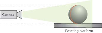
Next you need to place the rotating platform on a table, approximately
60cm (2') away from the camera and laser. This distance will
vary depending on the size of the subject to be scanned.
Do not have the camera and laser too close to the object. If
you are forced to use a wide-angled setting on your camera,
you can introduce barrel-distortion to your images. This can
affect the shape of the photographed laser line and distort
your object. It is preferable to place the camera further away
from the object, and then zoom-in. This will minimize the barrel-distortion.
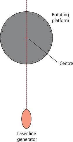
You should position the laser so that the line it generates
slices straight through the centre of the rotating platform.
You should be able to gauge this by eye.
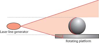
The
height of the laser should be at the centre of the object to
be scanned.
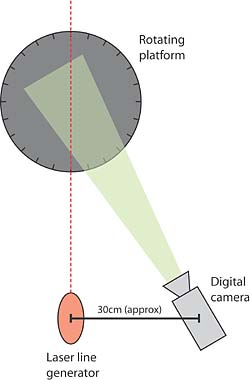
The
camera should be positioned on the right-hand side of the laser
line generator. The distance away from the laser will vary depending
on the subject matter. The further away, the greater the scanning
accuracy, but some highly detailed objects will obscure the
laser line if the camera is too far away. In these instances,
you should position the camera a little closer to the laser.
The setup I use has a number of holes drilled in the piece of
mounting timber, allowing me to easily reposition the camera
depending on the subject matter. If you are unsure what distance
to use, 30cm (12") is a good starting point.
The
height of the camera should be positioned so that the object
appears dead-centre of the viewfinder while the camera is completely
flat.
SCANNING
Realistically, when I say scanning, I really mean photographing.
You will be taking a series of photographs of the item to be
scanned from a variety of angles. The photo that you take can
have a significant effect on the end result. You MUST ensure
that the flash is turned off when you photograph. Wherever possible,
you should also try and photograph in very low light. Because
the laser beam is so strong, even if you can see nothing else
in the photograph, the laser line is all that is needed. The
digital camera I use has the ability to change the exposure
time and the aperture, allowing me to shoot very dark photographs,
even in the daytime. This is what you want to try and achieve.
Below is an example of one of my photographs.
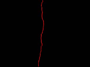
This
was shot in near darkness, and will produce a very good result
with the Scan Z line recognition.
STEP
1. Once you have all of your items in position, place the
object to be scanned onto the centre of the rotating platform.
Look through the viewfinder of the camera, and check that the
whole item can be seen. Swing the platform around a bit, and
be sure that the item will be contained in the frame of every
photo.
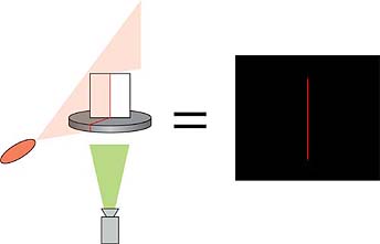
STEP 2. Now it is necessary to calibrate for the photo shoot.
To do this, you need a calibration item with a known height
and width. I use a piece of Fomecore cut into a rectangle 15cm
wide (6") by 20cm (8") high. I then attach another
piece of Fomecore at a right angle, so that the flat surface
can stand upright. Remove the object to be scanned from the
rotating platform, and temporarily replace it with the calibration
item. Place it in the direct centre of the rotating platform,
so that the laser line will appear as a vertical red line, shooting
right up from the centre of the platform. Take a photo.
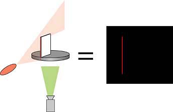
STEP
3. Now you need to calibrate a specific distance away from
the centre. My calibration item is 15cm wide, so I place one
end at the very centre of the rotating platform, and then rotate
the platform until the laser is drawing a line right down the
edge of the calibration item. This way the Scan Z software will
now know the exact location of 15cm away from the centre of
the platform. Take a photo.
STEP
4. Return the object to be scanned to the platform, and
make sure it is secure. It must not move for the duration of
the scan. Rotate the platform until the laser line is shining
on your start mark of your rotating platform. Take your first
photo. Rotate the platform to the next mark and take another
photo. Repeat this process until you have rotated the platform
all the way around. Now that the photos are taken, we need to
run them through Scan Z.
USING SCAN Z
STEP 1. Once you have all the photographs on your computer,
create a folder, and place your two calibration photos inside.
Now create a new folder inside this one, and place all of the
photos of your object inside.
STEP 2. Launch the Scan Z application. You will see two
windows: the main Scan Z interface, and the Status window. To
begin with we will look at the Scan Z interface. You will notice
that the interface is broken into two areas: Calibration and
Create Model.
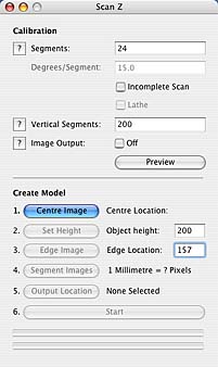
STEP
3. Enter the number of segment photographs you have taken
into the Segments field at the top of the window.
STEP 4. You will now need to decide what vertical resolution
you are going to use for your model. The figure you enter will
dictate the number of divisions for the full height of the photograph,
not just the subject matter. If your object takes up half of
the height of the image, and you enter a figure of 100, your
model will be split into 50 vertical polygons. If the figure
is too low, you may miss important detail from your scan. If
it is too high, you may end up with unnecessary polygons. You
may need to experiment with this figure to find the optimum
resolution. The demo version of Scan Z is limited to a resolution
of 40.
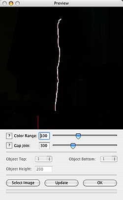
STEP 5. Because your lighting conditions may vary each time
you scan an object, you can calibrate Scan Z to adjust to your
photographs. This can be done interactively by clicking the
Preview button. This will open the Preview window.
Click
the Select Image button and navigate to the folder containing
your images. Select a photo from your image sequence. This will open the Area Selection window.
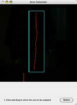
Click and drag around the part of the image that contains the red line. This process is so that Scan Z doesn't need to process any unnecessary data. Click the Select button. You will now see a small yellow square in the window.
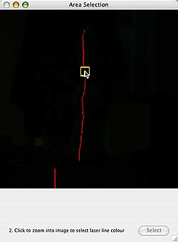
Using the mouse, move the yellow square over a part of the red line, and click the mouse button once. You will see a magnified view of the selected area.
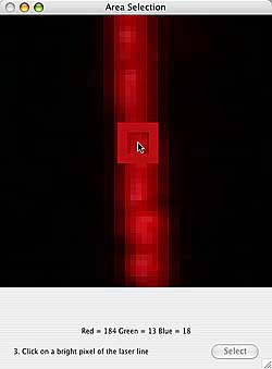
Navigate to a bright part of the laser line, and click the mouse once to select the colour. You will see the RGB colour breakdown at the bottom of the window. If you want to change your colour selection. use the yellow square to select another part of the image, and repeat the colour selection process. Click the Close button to return to the preview window. Scan Z
will now apply the selected settings to the image, and trace
a white line to show where it has detected the laser line. If
the line is incomplete, or displays like an Echidna (porcupine),
you may need to adjust your settings. If the line is not being
recognized, or if there are unwanted breaks in the line, you
will need to increase the Colour Range. The higher the Colour Range, the more of
the image tonal range will be scanned for the line. If your line is
appearing zig-zagged, decrease this value. The Gap Allowance value tells Scan Z what to do with breaks in the laser line.
In some instances, you may scan an object with holes in it,
which will cause the laser line to stop and start. In these
instances, you may want Scan Z to treat these areas as a hole.
Other times, the laser line may have ended up invisible to the
camera in certain areas, but the object still has shape there.
In these instances, you may want Scan Z to simply join the line
where there is a gap. By increasing the Gap Allowance setting, Scan Z will join larger distances. By reducing this
setting, Scan Z will leave these gaps as holes. This value is
based on the gap in the photo in pixels. Each time you make
a change to any of these settings, click the Update button
to see the results.
Once you are happy with the line recognition, click the OK button.
STEP
6. Now we return to the main interface window. Click the
Centre Image button, and select the centre calibration
image you took in Step 2 of the scanning part of the instructions. Select the scanning area and line colour as per the previous step.
STEP 7. Click the Set Height button and the centre
calibration image will be analyzed and then shown in the Preview
window. You will notice that there are now some more calibration
options available. We now have the Object Top, Object
Bottom and Object Height settings. Scan Z should
have automatically detected the top and bottom of the calibration
line, and the Preview window should show a green indicator
at the top and bottom of this line. If the line has become broken
into separate lines, you can use the pop-up menus to select
which start and end points of the calibration image to use as
your height gauges. In most cases, you should not need to change
these settings. Now you need to enter the height of the calibration
object. Select which units you prefer to use from the Units menu. The options are millimetres, metres and inches. I am using millimetres. My calibration item
is 200mm high, so I enter a value of 200. Scan Z can now
calculate the height based on the figure you have entered, and
the length of the line detected from the centre calibration
image. Click the OK button to close the Preview
window and return to the main interface window.
STEP 8. Click the Edge Image button and select
the edge calibration image you took in Step 3 of the scanning
part of the instructions. Select the scanning area and line colour as per steps 5 and 6. Enter the width of the calibration
object into the Edge Location field. My calibration object
is 150mm wide, so I enter a value of 150.
STEP 9. Click the Segment images button and navigate
your way to the folder containing all of your sequence photos. Scan Z will load all of the images into the Area Selection window, so that you can accurately make your selection. Use the slider to scrub through the images in the sequence. Make your area and line colour selection as per steps 5, 6 and 8.
STEP 10. Click the Output Location button and navigate
to where you would like your final obj file to be saved and
name the file however you wish.
STEP 11. Click the Start button to begin the model
construction process. One at a time, Scan Z will analyze the
photos and locate the laser line. The Status window will
show you which image is being scanned, and how long the process
has until completion. You will also see a preview of each image,
and the line recognition as the process takes place. Upon completion,
the preview will quickly animate all the photos that were taken,
followed by a cross section of the objects from top to bottom.
Now the output shape is created. An obj file will be created
at the destination you specified earlier. You can now open this
model into your 3D application.
NOTE: When you open the model, there may be some stray
vertex points. This is just a part of the model creation, and
they can be deleted. In future revisions, Scan Z will no longer
include them in the object file. It may also be necessary to
use the smooth function to help smooth out the points on the
surface.
EXTRA FUNCTIONS
In some instances, you may only need to scan part of an object.
Perhaps you have sculpted a face, and you don't want to scan
the back of the head. You can select the Incomplete Scan
checkbox, and specify how many segments you have, and what the
angle of each segment is. Scan Z will then only analyze the
number of images you have selected, and will only build a partial
model.
The other option is to Lathe an object. If you are scanning
an object that is cylindrical and symmetrical, such as a wine
glass or a beer bottle, there is no need to scan the whole object.
One photograph is all that is necessary. With objects such as
these, take your centre and edge calibration images as normal,
and then take one photo of the object. Select the Incomplete
Scan checkbox, and then select the Lathe checkbox.
You will notice the Segments field changes to '1'. Enter
the degrees per segment into the appropriate field. If you would
like your lathed object to have 100 segments, enter a figure
of 3.6 degrees (360 ÷ 100 = 3.6). Now follow the procedure
for a standard scan, but your object will be constucted from
the geometry of a single photograph only.
|