WHAT
YOU NEED
SET
UP
LIMITATIONS
OBJECT
SIZES
EXAMPLES
AVAILABILITY
The
SCAN Z do-it-yourself 3D scanner works on the same principle
as most other 3D scanners, the difference being that it is much
cheaper to setup, and the main components you may already have,
or can be sourced very easily.
WHAT
YOU NEED
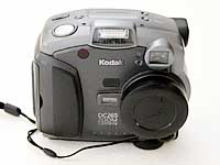
To begin scanning there are a few essential items. The first
is a digital camera. Almost any digital camera will do, as long
as it has a tripod mount hole at the base.
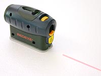
The
second is a laser line generator. This one is a GMC Redeye Deluxe
Laser Line Generator. I grabbed it from the hardware for around
$60. It also has a standard tripod mount hole.
The
third item is a rotating platform or turntable of some description.
I went out and bought this rotating television stand for around
$30. I then printed out a thin indicator strip all the way around
the base with marks at regular intervals. I have placed marks
at 15 degrees (24 segments), 7.5 degrees (48 segments) and 3.75
degrees (96 segments).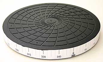
SET
UP
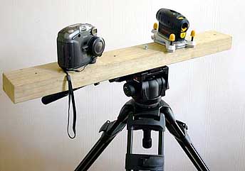
Now I set up the three items in a triangle.
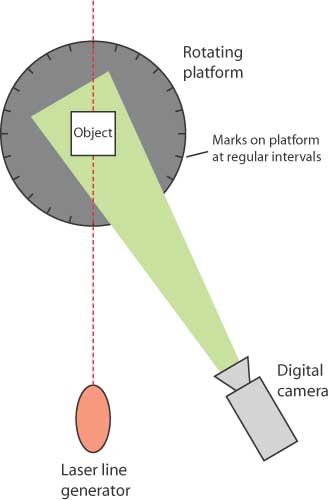
I
mount the camera and the laser line generator onto a piece of
timber, which is then mounted on a tripod. A tripod isn't entirely
necessary, as long as you have a way of securing the camera
and laser in position so that they can't move during a scan.
I then place the rotating platform on a table, making sure that
the camera is at the same height as any item on the platform.
To
begin a scan, I first calibrate the position of the camera relative
to the laser. This is done by placing a flat object onto the
centre of the platform and then taking a photo.
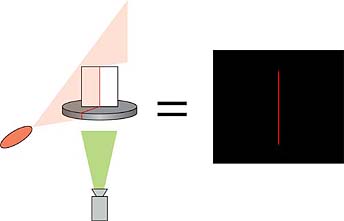
This
allows my software to calibrate its calculations to this centre
point. Next I calibrate a specific distance away from the centre.
I have a square block that I use that is 15cm away from the
centre point. I then rotate the platform until the laser is
shining on the edge.
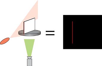
This
allows my software to find a unit of measure based on the distance
from the centre of the platform to the distance of the calibration
object. Now I begin scanning. I place the object to be scanned
onto the platform, and make sure it is secure. It must not move
for the duration of the scan. I then begin taking photos. By
using the marks on the platform as a guide, I rotate the platform
at regular increments, and then take a photo. For standard resolution
I use 24 photographs, and for hi res I use 48 or 96 photographs.
The number of photographs taken depends entirely on my requirements
and my patience. When the photos are taken, I run them through
Scan Z.
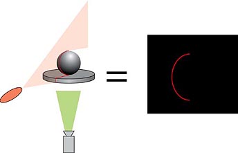
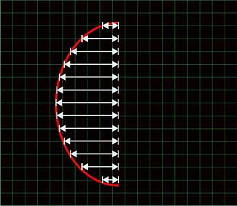
One
photo at a time, my software finds the red laser line in the
image, and then plots a location in 3D space based on the object
contours, the degree of rotation and the calibration figures.
My
software processes all the data and then creates an obj file
that can be imported into most 3D applications.
LIMITATIONS
I'm afraid that this system does have some limitations. Firstly,
all it can capture is the geometry of the object, and not the
surface map. You would need to create your own surface maps.
Secondly, due to the way the object is scanned, you will never
capture everything. The laser line will always fade away at
the very top and very bottom of the object, meaning that you
won't be able to capture these areas. Some level of manual modelling
will need to be done for almost all scans. Also, it is unable
to capture parts of an object that will not reflect the laser.
For instance, if you were scanning a coffee mug, you would not
be able to capture the inside of the mug. The laser would not
reflect off the inside surface, as it would be stopped by the
outside surface.
Thirdly, the accuracy of the final model depends a great deal
on the rigidity of your setup. If the camera, laser or platform
wobble or shift during photography, you can end up with bumps
or irregularities in your object. Finally, the object created
can only reflect what can be traced by a laser line. Some complicated
objects may end up with areas that cannot be traced do to the
laser being obscured by protruding parts of the scanned object.
OBJECT SIZES
The maximum object size depends on the scanner set up. With
the set up you see here, you could scan an object from around
5cm (2 inches) in diameter up to about a metre (3 feet) in diameter.
The limitations are based on whether you can get the object
onto the rotating platform, and whether the laser beam is still
visible on the surface of the object.
The resolution, or polygon count of the output file is dependant
on a few things. Firstly, it depends on how many photos you
take of the object. If you take 48 photos (every 7.5 degrees),
each vertical segment will have 48 polygons. The number of vertical
segments is dependant on the quality of the photograph, and
the resolution setting used in Scan Z. If for instance you chose
a setting of 100 as your vertical resolution, it will split
the object into 100 vertical segments, so you would end up with
100 x 48 polygons, or 4,800 polygons.
EXAMPLES
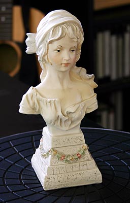
So far, I have not completed many scans, but as I do I will
post more examples here. For now though, here is an object I
scanned. It was scanned from 96 photos, which took me around
5 minutes to photograph. The software took around 5 minutes
to process the images into a 3D model.
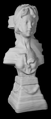
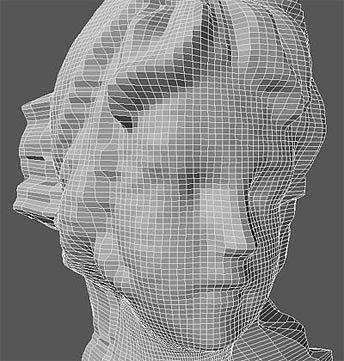
And
here is the scanned 3D object. The scanned object has NOT been
altered or improved in any way, other than some phong shading.
This is the raw object generated by the software.
 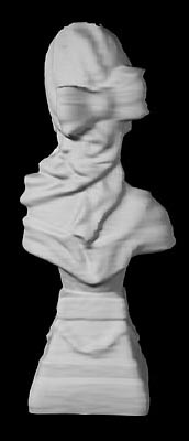
Here
is a close-up of the polygons from the face area. Keep in mind
that the face of the original statue is only 35mm (1.3 inches)
wide.
AVAILABILITY
I have not yet even decided on a price for this software, but
I will be selling it as a cheap alternative to what is already
out there, so it will be very affordable. If you have an opinion
on the value of such an application, feel free to send me an
email.
If you would like to be a beta tester,
fill out the online form here.
If you have any queries, please send me an email via the link below.
|